I've spend the summer holidays on a little project, namely a fanbus.
Yeah yeah, another fanbus ?
No, this fanbus is somewhat more advanced than standard ones, it's software
controlled – the outputs are controlled via software instead of switches,
using the parallel port. (Tough luck for owners of Abit MAX and other legacy-free
motherboards..)
Furthermore the software also has the extra feature that it can be integrated
with the temperature readings from Motherboard Monitor – which therefore
means that the fanbus can automatically turn fans on and off when the system
reaches certain limits.
This guide is primarily meant as inspiration for people with at least a basic
idea of electronics, but who have not thought about using their knowledge
for a project like this. I wouldn't recommend starting on it unless you have
some experience in electronics – it is, after all, your computer that the
fanbus will be connected to, and you are putting it in possible danger!
With this guide I hope that those interested and skilled enough can use the
ideas for extended and/or improved designs, and that we will therefore get
to see even better versions.
I'll be happy to assist if anyone has any further questions about the ideas
and principles presented here.
Note, however, that this fanbus should NOT be used for
critical fans, first and foremost because they might not be started before
Windows has been loaded and the program started, secondly because the program
of course cannot react if Windows has already crashed with a BSOD due to
overheating.
The project is split in two parts, software and hardware.
Hardware - introduction:
The circuit itself is actually pretty simple, but might be a bit confusing
at first if you haven't dabbled a bit with electronics before.
There are a total of 5 outputs, each capable of 1 ampere, however, these
can quite easily be upgraded to higher currents if needed.
2 outputs can be changed between 0 or 7 volts, 2 outputs between 0 or 12
volts, and the last can be either 0, 7 or 12 volts.
Looking back it would probably have been smarter to design it with 3 outputs
with 0/7/12 volts, but this is of course easy to do yourself by making three
0/7/12 modules.
If I get the time I think I'll make a new version with three 0/7/12 volt
outputs, but right now I've run out of components.
I'd also have preferred using serial or USB ports, and have had stepless
adjustable outputs, but this would've required a microcontroller or something similar,
and I was kicked out of school before I got the hang of them.
Software - introduction:
The controller program “CKControl” is written using Borland C++ Builder 4,
and *of course* it works under both DOS-based operating systems (Win95, Win98,
WinME) as well as NT-based such as 2000 and XP. (Ok, it's only tested under
98SE and 2000, but it should work on the other ones also.)
The code isn't very pretty from a programmer's point of view, there are many
global variables, some repeated code and some “hacks”, but seen from a user's
point of view it works fine, uses only 700-1500 KB of RAM and immeasureably
few CPU resources.
Diodes:
2x 1N4148
1x 1N4001
5 green LED's. (Blue should be fine too.)
Resistors:
6x 10 K
1x 22 K
5x 100 R, 1 Watt (they get pretty hot.)
5x 470 R
1x 330 R
Furthermore you'll need a veroboard, some wires, LED holders, screw-in wire
holders for the PCB, some Molex-connectors for the outputs, and of course
a parallel cable. The components shouldn't cost more than around 15-25 $
at most, primarily depending on how much you spend on LED's, LED holders,
veroboard and other miscellanous stuff, and if you can find an old parallel
cable or if you have to buy a new one.
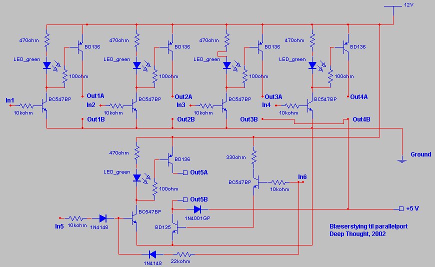
The diagram
Comments:
The circuit is more or less modular, with the two 0/12 volt outputs top left,
and the two 0/7 volt outputs top right.
If the input is HIGH the output goes HIGH. Simple transistor circuits, with
an LED to indicate if the output is HIGH.
Not much to say about them.
In the lower part of the diagram you can see the circuit I cobbled together
for the 0/7/12 volt output.
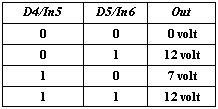
It's controlled by output 5 and 6 (D4,D5) on the parallel port, with this
truthtable:
In short: if D4 is HIGH the output is at 7 volt, unless D5 is HIGH where
the output will be 12 volt.
The diagram could probably be extended/enhanced in certain areas, but unfortunately
I ran out of components.
However, I'd especially recommend some pull-down resistors on the bases of
the two BC547B's in the 0/7/12 volt circuit, and sticking a LED somewhere
to indicate that the output is at 12 volt.
Some more powerful output transistors, some protection diodes over the outputs,
and some “override” switches for manual control of the outputs might also
be a good idea.
If time permits I'll possibly improve the circuit and update the article
at a later date.
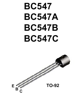
For now, here are the pin connections for the transistors I've used:
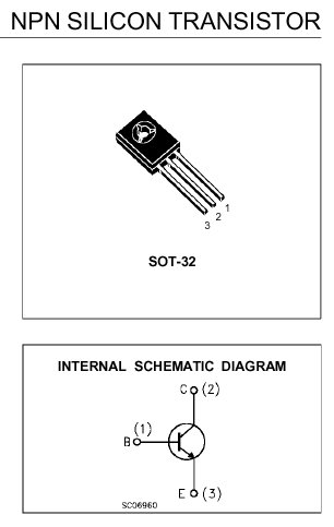
And the BD135/BD136:
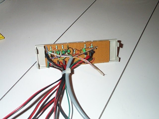
Parallel port connections:
The cheapest way to get a parallel cable for a project like this is of course
to “organize” an old printer cable, and just cut it to a sufficient length.
However ,you should be aware that it's very rare that all of the pins in
the cable are connected, especially doubtful is it if all of the ground-wires
are.
You should make sure that you're using the correct wires, better measure
it in case the cable is a bit “strange”.
Or you could of course pretty easily make a useable cable yourself, if you
buy a male DB-25 connector and find a multi-wire cable.
The interesting connections in this case are:
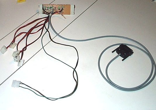
Some pictures of my result:
Almost completed test design:
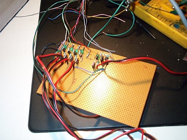
Glued to a 5.,25” drive cover.
The LED's should have been turned around so they could be seen from the outside,
but that's got to wait till I can make a new version.
The final result – which is currently in use in my system.
This means that I may only release the compiled .exe itself, but fortunately
I was allowed to also release the source code showing my implementation –
thanks a lot, Craig Peacock!.
Motherboard Monitor integration:
Access to Motherboard Monitor's “Shared Memory” was made possible using code
with these restrictions:
// ---------------------------------------------------------------------------
// --------------------------------------- Copyright 2001 A@majland.org ------
// --------------------------------------- Alteration for use in Visual C
----
// --------------------------------------- By Chris Zahrt techn0@iastate.edu
-
// ---------------------------------------------------------------------------
//
// Version : 0.1
// Date : 02-27-2002
//
// MBM : version 5.1
//
// Author : Chris Zahrt techn0@iastate.edu
(visual c alterations)
//
http://techn0.dhs.org/programming/vcmbmsm.html
//
Anders@Majland.org (author of original c code)
//
http://www.majland.org/sw/mbmcaf
//
// Licence : Cardware. (Send me a note/email
if you find it usefull.)
//
Basically you may use it as you see fit as long as the origin
//
of the code remains clear
//
// History :
// 0.1 02-27-2002 conversion
of 0.3 borland to this version
// Update for MBM 5.1.9 by Bill Nalen bill@nalens.com
Integration with Motherboard Monitor *requires*
that you're using version 5.1.9 or newer, the newest at the time of writing
is 5.1.9.1 – this is due to the format of the shared memory which has been
changed from prior versions.
Download:
My program, CKControl, can be downloaded here:
Windows NT requires a device driver, porttalk.sys, which can be downloaded
here:
Put this in /WINNT/system32/drivers/
The source code for CKControl will be uploaded when I get it cleaned up a
bit.
CKControl: Usage and comments:
The main menu:
“All outputs on” and “all outputs off” are quite obvious, and are basically
remnants from the development phase. Still, they might be useful for something
and are therefore still enabled.
“Hide” hides (oh really?) the main window, doubleclick the icon in the tray
to reopen it.
“Close” saves the program's settings and closes it. (The settings are saved
in “CKControl.ini” in your Windows folder.)
The four buttons to the left are used to turn on/off the different outputs,
the last one changes output 5 between 0, 7 and 12 volt and back to 0 again.
When Motherboard Monitor is used to control an ouput the corresponding button
is deactivated.
In the five large text boxes you can enter a little note about what the different
outputs are used for, which is also saved in CKControl.ini
Port addresses: Standard computers usually only have a single parallel port,
LPT1, with the address 0x378.
In case of special configurations, or if you're smart enough to obtain and
use a separate printer port to lower the risk of killing your motherboard
in case of shorts or failure in the fanbus, the other ports can be setup
here.
“About” curiously enough just opens this window:
Other features:
To avoid that an output controlled by Motherboard Monitor, where the sensor
is just around the activation temperature, is being turned on and off whenever
the sensor hits the threshold for just a short while, the outputs will only
change when the sensor for 15 seconds has been on or above the threshold.
The program also supports “command line parameters”, if you need them for
something – for instance if you just want to activate the fanbus but don't
want or need to have it running constantly.
Parameters: (not case sensitive.)
1:on, 1:off – turn on/off output 1.
2:on, 2:off – turn on/off output 2.
3:on, 3:off – turn on/off output 3.
4:on, 4:off – turn on/off output 4.
5:off, 5:7, 5:12 – set output 5 to this voltage.
Minimize – minimize to tray after starting.
Shutdown, exit, close – close the program after outputs are adjusted.
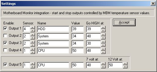
The “MBM integration” button opens this window:
Here you chose which temperature sensor should control each output, and at
what temperature they should change.
“Name” is the name you've given the sensor in the settings for Motherboard
Monitor, and “Value” is the current value.
I hope you've been inspired by this guide.
Please send questions, suggestions for improvements or corrections to me
so the guide can be updated/corrected and “we” can make the “ultimate fanbus”.